My Tractor Forum banner

Snapper 331416BVE Riding Mower Model 1433

3.9K views 15 replies 3 participants last post by  propwash  
#1 · (Edited)
Snapper 331416BVE Riding Mower Model 1433 will not move

Mower has been working well for the last few years but while mowing about a week ago it just stopped moving. I pushed it back to level ground and started it back up. When i put it in 1st it barely tries to creep forward and it does nothing in reverse. I did some searches and thought it sounded like it was the drive disc so I ordered one and replaced it yesterday. With the new on installed it is still doing the same thing.

What else can be wrong? Is there some adjustment to make the disc tighter like it is may be slipping? Could the chain have broken? When I turn one wheel the other one spins the opposite way if that would be an indication that it isn't broken since i'm sure it has always done that. When i put it in 1st it just very slowly creeps forward maybe a couple of feet in 15 seconds and not really at a steady rate, it kind of inches forward, stops, then inches forward. When i do engage it into gear with it tipped up the wheel is hard to turn but I can make it slip with a wrench. Also if I spin the disc by hand with it tipped up the wheels do not turn at a rate I would expect. I would think once the slack was taken out it would just spin real slow but something seems wrong.

Any ideas would be appreciated.
 
#2 ·
bob: we just had a posting on an earlier RER with a similar problem . You might review that post (3311sc won't drive) , as we suggested several things that might be wrong , his problem was a broken/missing "hub bolt" . If you review the last illustration I posted in answer to tomw0 ,this is the set-up on your series 16 .This series has been "simplified" in the area of the "clutch linkage" and doesn't have as many parts to wear out or fail . The fact that yours tries to pull in the forward "gears" and not at all in reverse , might mean that the problem , isn't in the "gear/chain" area , but maybe in the "yoke" area , either the "slot" in the yoke or the "yoke bushings" .
 
#3 ·

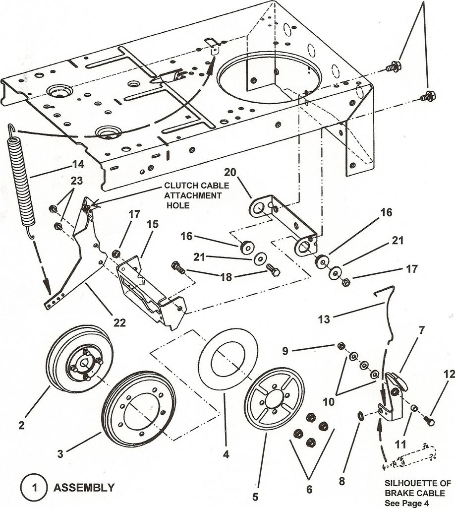
I reposted the illustration , of the "clutch parts" , for series 16 & 18 from that parts manual . I understand from looking at your earlier post , that you have had this machine since 2010 , if this is the first "driven disc" that you have changed , you should have no complaint , I seldom get more than 2 or 3 years on one .The first thing to check is that you got the right disc , there are 2 different set-ups for RER's yours should be the "smooth" clutch , it has a "liner" in the disc on the side nearest the hub , it's usually a green paper like strip . if you don't have that it's the wrong disc . When doing the "opposite turning check" that tests the differential gears , not the chains sprockets ,and other "reduction gears" . when turning the wheels in the same direction , the disc should turn . If that happens with no jerks or gaps , the "internals" should be intact . The "location of the "
drive disc" on the engine crankshaft is sometimes suspect , but it was probably set at the time of the Tec. engine being installed , and it usually takes some work to move that after it has run for a long period . The next suspect is usually involving the "yoke" item #15 in the illustration , the "tail" of the chaincase runs in the groove to change speed and direction ,of the driven disc .The "yoke "snaps" to hold the chaincase "tail" in the proper position the sleeve on it should turn easily , and not be "grooved , and the yoke should not be worn , nor the "nylon" bushings #16, that it pivots on . the spring#14 is what holds the "rubber" disc against the steel Drive disc , and you can see ,it has 4 "mounting holes" to adjust the tension . The clutch cable runs from the L/H side to the pedal .
 
#4 ·
Ok, here is a video that shows with the drive disc off. I'm sure I ordered the right one, you can see it laying on the floor in front of it. Sometimes the hub spins when i do spin the tire sometimes it looks like it must be slipping. if i turn the other back wheel it doesn't do anything.


Let me know if i need to do anther video to show you more.
 
#6 · (Edited)
If you can spin both the wheels together while holding the hub , I would suspect the key between the hub and shaft , but one wheel could be just the differential working like when one wheel is in the mud , and it just spins while the other one on dry ground doesn't drive. The disc in the video has the "liner"
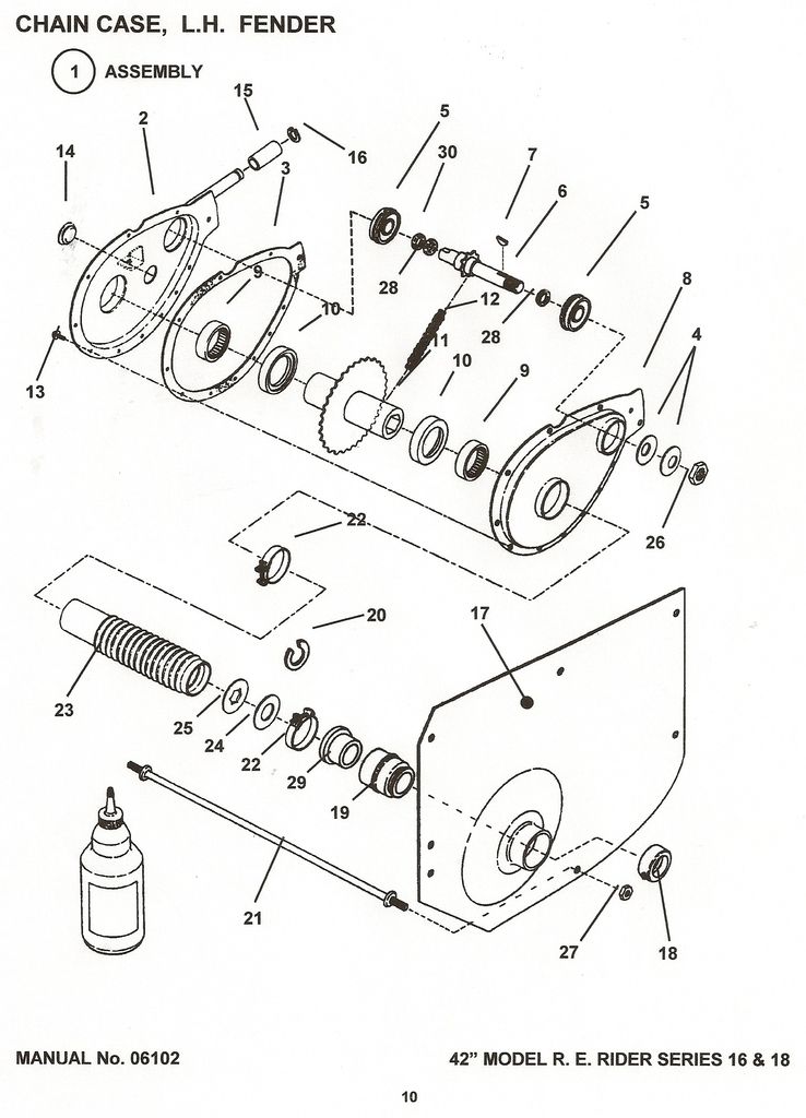
if it's the key it's #7 PN7010614 a "1/8 X 5/8 woodruff key" the hub #2(shown in a previous illustration) is usually ruined, and it's PN 7054243
 
#8 ·
The only moving parts in the chaincase are the upper shaft or chain which could be worn enough to "ride off the sprocket' or the large "hex drive" sprocket . you might try just holding or moving the nut #26 ,and see if that is different , if it acts the same then , it should eliminate the hub and key , from being the problem . the key might have not sheared "cleanly" , and still tries to "drive" a little . Also try the other wheel and see if it does the same thing
 
#10 ·
Yeah that would be it , if you can break the nut loose , the shaft turns the works , and tries to drive the tires . . The shafts that drive the hub vary over the years , some have a brake on the other end ,some look like they might have "flats" on the other end setting the brake on the later ones won't help , as the brake works on the back of the hub , and doesn't hold the shaft. I've never done it with a sheared key ,maybe some other member can help .You might pull a boot back from the chaincase , and hold the "hex tube with a wrench , but be careful It's soft and bends easily.
 
#11 ·
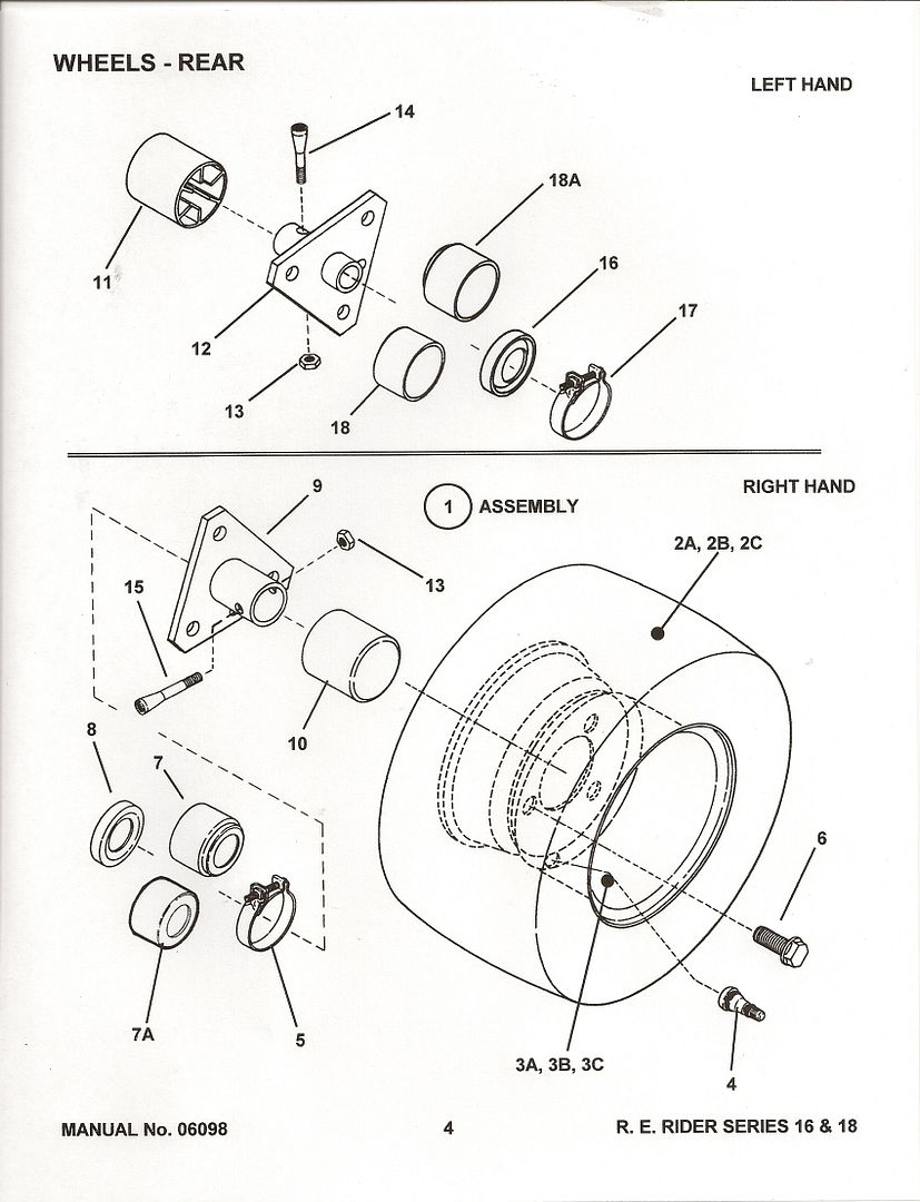
Ok, I figured out what was wrong. The pin that goes through the left rear wheel and the axle has sheered off and fell out. I was loading it up on a trailer to have someone else take it apart and find out what was wrong and I noticed that the wheel on the left rear was closer to the frame than the right rear. I looked at the left wheel and noticed that the axle was sticking out of the center of the wheel about 1/2 inch. I then examined the right wheel and saw the there was a pin with a nut going through it. The whole time the axle was actually spinning around in the center of the wheel, since the pin had broken and fell out, and I guess just the weight downward on it made it drive it forward just an inch or 2 at a time on smooth level ground, but mostly just slip. I wish I would have paid attention to how the rear wheels were attached, but I have never removed them since I have owned this mower. Lesson learned.
 
#14 ·
I use the term "bolt" because that is what Snapper calls it , I assume that posters use the Snapper manuals . It is technically a "taper pin" retained in the hole with a nut. the nut only serves to hold the pin in position , when installing a pin I "rap" it ,with a hammer, on the un threaded end , to "seat" it and check tightness whenever working in the area ,it doesn't need to be "super tight" as it only keeps the "pin" in position. And "Snapper Trout" recently had the same problem.
 
#15 ·
DC3prop can you elucidate the difference between the two side pins? Every time I have gotten one, it has been the same thing as far as I can tell. They always deform over time, and tend to wrinkle the hub and the edge of the hole in the drive axle. I have used a grinder in a drill and a file to 'dress' the holes to allow hub installation and a good pin 'fit' just because it seemed the right thing to do. Is there a better procedure? I noted that the 'pins' are not round, and the partial flat is to be parallel to the direction of motion. What were they thinking?
tom
 
#16 ·

tomw0: a good illustration of the "wheel bolts" . L/H 7011035 1&3/8" long and the R/H 7011013 2" long The main difference would seem to be length overall ,with the "taper" probably the same size. I'm sure the taper is not the precision kind found on flywheel / crankshaft or ,Old Ford axle /hub fits. the threads are shown 5/16x24 and the hole would be a little bigger than 5/16 , and the taper bored or Punched into the axle while hot .both the axles and the hubs would have 2 different size holes ,and would be installed to fit .The more "slack" between the hub , and the "bolt" the faster the wear