My Tractor Forum banner

Design for a homemade front end loader (FEL)

268K views 84 replies 32 participants last post by  MARK (LI)  
#1 · (Edited)
Here's a few cad drawings of my loader design. Enjoy, use, build one for yourself!!

Image


Image


Image


Image


Image


Image
 
#6 · (Edited)
:ditto:

Try 2 x 4 x 1/8" tubing with 1/4" plate at the stress points and the mounting holes in the arm ends could be schedule 40 pipe welded into holes drilled through the tubing, rather than 1/4"plate extensions, to better support the loads.

Your cross member isn't large enough to deal with the wracking of the arms from asymetrical loads on the cutting edge. Try 4 x 4 x 1/8" tubing there, and watch your hood clearance.

The attachment of the posts to the subframe is a little worrisome, and a better look at the subframe and its attaching points would be helpful. Without a brace from the top of your posts to the front of the tractor, the torque load at the bottom of the posts will be enormous, about 6' times the load in the bucket, or 600 ft. lb. for every 100 lb payload.

The subframe is the foundation for the loader. If it won't handle all the forces generated by the use of the loader, most light GTs will have a problem dealing with what's left over. I broke my MF12H in half 3 times before I figured that out. That was 30 years ago. I only had one similar problem on my MF1655 in 23 years and that was laziness on my part. I knew the problem was there and didn't address it.

There are many different forces acting in several different directions at the same time with a FEL. The lifting forces meet at the front axle pivot.

Your arms, as drawn out, will be good for about 1.5 tons in the bucket, if you have enough counterweight. The post mount, only about 200 lb............. maybe.

Good basic design. Just needs some tweaking.

Check this thread for more info.

http://www.mytractorforum.com/showthread.php?t=175389
 
  • Helpful
Reactions: MTFSupport
#7 ·
I have trouble accepting criticism, but i'll do my best. Thanks for the tips. This design is no where near finished, that was just something i whipped up in a couple hours that morning.
 
#9 · (Edited)
Putting a project in a thread invites comments and criticisms. Especially when you prefice the post with this statement:

Enjoy, use, build one for yourself!!

This statement indicates that the design is complete and ready for someone to fabricate and use, not something that was "whipped up in a couple of hours" and is actually in need of much revision to make it safe and effective.

My previous post falls under the heading of "hints and guidance", not criticism.

You're welcome to the tips and there are more if you're interested. :fing32: (Sure wish I could do CAD work!) :Disgus:
 
#8 ·
It's a starting point, and that's what matters. I'll probably take that basic design with some mods like a Bobcat-style quick attach system instead of permanent bucket, and maybe even a drive-in quick attach for the frame.
Lawn tractors aren't really universal, so everyone will have to figure out how best to integrate this with their tractor. Don't worry about that part too much, especially on free plans.
 
#12 ·
Tudor, thanks for the input. Not knowing about the multiplying forces an FEL produces could have left me building "as drawn".

Chuck, thanks for the prelim drawings. I hope to see the various issues addressed to make a better design. For my purposes the build could be lighter, say a 500 lb lift. I'm not sure I even feel comfortable with that weight on a JD 314 or Simplicity 3012, as would be my current options.:fing32:
 
#14 ·
I thought the whole purpose of the forum thing was to share and collaborate so everyone can benefit from the experiences of all.

Dan's suggestions are right on. Having personally performed the structural analysis on New Holland Skid Steer Loaders and some of the older compact tractor loaders, the critical stress points are the tie-in to the frame and the loader boom cross tube. The idea behind the frame tie-in is to triangulate and truss everything so that your primary loads are tension & compression, not bending. That's why most loaders have that diagonal member from the front of the tractor frame to the top of the towers. The cross tube does indeed take all the racking in the boom. The more section you have the better. Big diameter, thin wall is best. Then the challenge is tying it into the loader arms with out creating weld fatigue points. Anyone want to post up some sketches of stuff they are working on, I'd be happy to comment. I don't get to work on loaders anymore (that engineering is done at a different location now), but I still do the same thing on other machines everyday.

- Dave
 
#15 ·
Chuck you should rethink your decision, TUDOR is a tremendous asset to have as a sounding board for projects his knowledge and experience is amazing.He as always presented advise to people in a positive way . It is a shame that you reacted this way , but I would bet he would continue to help you to fine tune your first revision of your loader design if you chose to finish what you have started.
 
#19 ·
I'm sorry you have an issue with my delivery, but I'm a one finger typist and posting in a way to prevent inadvertant rouffled feathers uses up time. My posts are mostly technical in nature and sometimes take me several hours to write, rewrite and edit and I prefer to utilize that time to impart information that will make improvements to the project at hand rather than making long winded suggestions that impart no hard information but are easier to swallow.

I worked in heavy industry and when a load on a crane is swinging towards someones head, I will yell "Duck" rather than say "Perhaps it would be wise if you lowered your head" at a lower volume that he may or, more likely, may not hear with the surrounding noise level.

You are dealing with a piece of machinery that does not care what you think, only with what will affect it. Please take my posts with the same attitude that you would have for any technical brief.

My primary concern is safety. My secondary concern is functionality of the equipment. Sugar coating is something done with placebos.

Ask, and I will give straight answers. If you would prefer not to read those answers, I will, of course, refrain from posting on your thread.

Your call, not mine.
 
  • Like
Reactions: Whitey1983
#18 ·
I'm confused here. I'm not understanding what was so upsetting to you about his initial comments regarding your design. From my perspective, it seems like you just got upset because he didn't go on and on about how wonderfully perfect your design was.
 
#20 ·
I've made some modifications. Please note this may not be a final product, any manufacturing of this product must undergo proper safety and efficiency test for your specific application. Please only use these drawings as a point of direction and not actual blue prints for a working design. These drawings are the personal opinion of Chuck21387 and only opinions...

enjoy the pics

The front cross tube is now 3 1/2 OD pipe with 1/8" wall, all tubing is now 2x4x1/8 wall
Image


Image


A bottom view of the subframe beef up, two cross bars at 1 1/2 by 1/8 wall, and then the front triangulated support is 1/4 x 3" strap. I may weld a perpendicular angle to the strap to keep it front bending or flattening during compression and tension loads.
Image


Image


Go ahead TUDOR, load me up with whats wrong now and i'll fix those next....I imagine i'll have some brackets to make for the dump cylinder to mount to the cross tube, and the bucket needs reworked in CAD but i'm off to celebrate my 7th wedding anniversary. I'll make changes as needed when i return.

I'm not the kind of man to run from a challenge, so i want TUDOR and myself to come up with a COMPLETE design for you guys to use for your tractors. Of course each tractor will have it's own differences in mounting, but if you're capable of fabbing this kind of stuff, you'd better be able to fab up some brackets for your own subframe. When in doubt, add some 1/4 plate :-D

I apologize to TUDOR...i told you i don't do well with criticism
 
#22 ·
Congratulations on your 7th anniversary.

Apology accepted with appreciation. It is not my intention to cause any stress on any member, we all want you to be here and throwing out your ideas for comment for many years. Sometimes an idea will trigger another thought that puts a whole different slant on a project.

Your redesign is much better and requires much less tweaking. My thoughts here are for the diagonal brace. Flat stock under compression does not maintain stability if there is any movement in the loader subframe when the bucket is loaded. Your idea of adding an angle to improve that stability is good, but involves an extra step in the process. Many GT loaders use pipe for those struts. After my experience with pipe struts for the self levelling feature on my loader, I prefer square tubing which is much more stable than pipe when in compression mode. Inch and a half would be my minimum recommendation for a small to medium GT, 2" for heavy GTs. The struts on my MF1655 are 2x4x1/8, but my original intention was to use them as the hydraulic reservoir. I ended up using the posts instead, but since the bracing structure was made, I used it.

If you are going to use a single cylinder dump, the pipe may be fine, but a square section will be stronger. The dump feature is also used when backblading with the bucket, usually with the front wheels in the air. Lots of stress going through that cylinder.

Wish I had a camera to show what mine looks like.

Supper. Later.
 
#26 ·
Cool, i put a round cross tube in because that's what all the BIG loaders use...i took a bunch of photos of the new Kabota loader on my buddy's 145hp tractor he got.

I later thought about using tube, or heavy angle for the triangulated support, the other key i want with this design is that a guy with a measuring tape and an angle grinder COULD make this (and a welder of course). So my drawings won't have many angles dimensioned out, or they'll be double dimensioned (which i know is a no no in the CAD world)

More work later, wife's getting ready for the day, i gotta go!
 
#23 ·
I built one years ago for my MTD 990. I made mine out of 1 X 1 square tube with 1/8 walls. Kind of a truss design. The posts were 2 X 4 X 1/8 tube. Would pick up around 300 pounds. Which was asking quite a bit of the front spindles. It worked well for years. Only problem was one of the lift cylinders had a hose come off and when lifting with the one cylinder one of the arms bent a little. The whole thing ready to work was probably around 200 #.
 
#24 ·
Am I correct in assuming that the black shape in your drawings represents the tractor frame?
 
#31 ·
That's how i usually roll when i do things around the house, but if i'm trying to make an effective loader for the every day guy, maybe he can't afford 1/4" wall tubing...so i'll go with TUDOR's recommendations on my drafting and design, then i might do 1/4" wall just cause it's what i've got, or cause i'd rather break the frame of the tractor, than the loader :)
 
#29 · (Edited)
I'm in no way an expert........but since you have such great skills with Auto-Cad, is there a way to design the under support attachment to be similar to the Johnson GT FEL? On the Johnson FEL, I noticed it has a tubing frame that mounts to the rear axle as well as the frontof the frame above the front axles. I would think that would possibly distribute the weight of the FEL (as well as the load weight) forces on a bigger platform? Perhaps I might have missed the design idea behind that concept, but it looked like it would put less stress on the GT frame and put more weight on the GT axles. On the Johnson frame, IIRC, actually had the frame mounted in that way, to carry the weight independent of the GT frame in the middle, by placing weight directly over front and back axles. It might not be always achievable depending on the GT brand. The uprights were built onto the frame and braced to handle the FEL lift arms.
 
#32 · (Edited)
Here are some links with some photo's on a Bolens GT, showing good photos of the front mount system of the Johnson and other links with phot's of the back and a good link to same loader off the GT before it was installed.

http://www.mytractorforum.com/showthread.php?t=151787&highlight=johnson+fel+front+end+loader

And another with a photo of the back part mounting the rear axle.....

http://www.mytractorforum.com/showthread.php?t=111634&highlight=johnson+fel+front+end+loader

And another link to show it off the GT before it was installed....

http://www.mytractorforum.com/showthread.php?t=110064&highlight=johnson+fel+front+end+loader
 
#34 · (Edited)
Some excellent points being brought out that are sometimes missed with homemade FELs. I'll try to explain some of the critical areas without too much preaching to the already knowledgeable, but also with enough detail for the novice to be able to fabricate a FEL that won't break in service or break the tractor at heavier loads. This not meant to be used as a "blueprint" but as a source of information to assist with modifying any specific plans to the requirements of the individual tractor.

The Subframe

This is the foundation for a FEL and the primary protection device for the tractor frame. The tractor frame keeps all the parts in place in relationship to each other, but in reality does not need to be all that strong in its own right, except at the front end from the front back to the front axle and approximately an equal distance behind (the front axle support box). This area will, at some point in the life of a FEL equipped tractor, be required to support double the weight of the tractor and any attachments or counterweights, probably many times. Even a light guage stamped frame will survive if a properly constructed, full length, subframe is used.

Subframe attaching points are the rear axle and the front axle support box. Intermediate attachments are not required, but the attachment fasteners should be sized to handle the UNexpected loads. See below for the force direction to be dealt with.

Post Support

This is usually a cross bar(s) fabricated as an integral part of the subframe, but may be bolted to the subframe with properly sized fasteners. See below for the force direction to be dealt with.

Post

The posts often double as reservoirs for the hydraulic fluid and should be sized accordingly. Some may desire a detachable loader and that capability will need to be accomodated with the fabrication of the posts and the method of attaching them to the post support. See below for the force direction to be dealt with.

Bracing

This part of the structure may be optional depending on the post and post support construction, but there is some serious math involved to make it safe. Improper design and/or fabrication will result in catastrophic failure at the most inopportune time and with a load that you don't really want to hit the ground hard. After that, Murphy takes over.

The bracing struts should be fastened to the post within a few inches of the top and to the front axle box or the front of the subframe. Service access to the engine bay will have to be taken into account when making and attaching the braces.
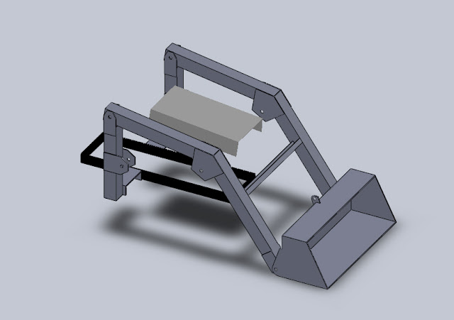
Loader Arms or Boom

Commercial loader arms are generally 1/8" steel box sections. Some are tapered from small at the ends to tall at the break in the arms. Others use square (2x2) tubing or rectangular (2x3) tubing. Many home builts use rectangular (2X4) tubing. Anticipated loads are the governing factor. Figure the heaviest load you plan on lifting, then triple it for choosing the the section for the arms. See below for the force direction to be dealt with.

Boom Cross Tube

This piece should be at least square and as large as will fit to the arms or optionally rectangular with the smaller dimension the same as the arm material it mates to. Its primary purpose is to prevent the racking of the arms from asymetric loads on/in the bucket. Its secondary purpose is to provide a surface for the hydraulic lines that go from one side to the other of the boom to be secured.

If a single dump cylinder is used for the bucket, it also provides a stronger attaching point for the base end of that cylinder and an easier fabrication of mounting brackets than a round section.

The position of the cross tube on the arms should be in the top third of the lower part of the arm. Care needs to be taken to accomodate hood opening when the engine isn't running, and hood clearance when raising the arms. Make a habit of parking the loader bucket in the full dump position, and maybe on a block of wood to facilitate opening the hood.

Forces - General Direction

Subframe - The front of the subframe deals with force in all 4 directions. The heaviest is vertical down when lifting a fully loaded bucket since it is also lifting the rear of the tractor as a counterweight at the same time. The lightest is vertical up when lifting the front wheels. Horizontal front and back deal with entering a pile of dirt and backblading with the bucket.

The rear of the subframe also deals with 4 forces. The vertical up is not as extreme as the front vertical down connection since it only has to deal with tractor and counterweight. The vertical down component is almost nonexistent since the empty bucket and that part of the arm assembly ahead of the front subframe attachment acts as a counterweight for the mass of the loader which is behind that attachment. When lifting the front tires, there is more downforce on this connection, but it relatively light in comparison to the upforce. Horizontal front and back forces are shared with and essentially the same as for the front attachment.

The reason for connecting the subframe directly to the axle took me a while to learn. When pushing into a pile of dirt, at some point the bucket stops. With enough traction and some flex in the tractor frame, the rear wheels may not stop until after the bucket stops moving. The result will eventually be a broken frame.

Post Support - Again 4 forces with the major force being vertical up when lifting, a minor vertical down when lifting the front wheels and the full horizontal front and back that the subframe has to deal with.

Post - If no bracing is used, the torque load on the post bottom connection gets positively scary. A 500 lb load in the bucket translates into something on the order of 3000 ft. lb. of torque load to be shared by the 2 post connections. With bracing, the triangle keeps everything stable and the hydraulic cylinder, in conjunction with the arm pin and post support, supplies a bending force to the post.

Bracing - The force is longitudinal and in compression or tension depending on if the bucket is lifting a load or pushin the front of the tractor up off the ground.

Loader Arms or Boom - The post pin end is subjected to a compound force. The cylinder is trying to push the arm away from the post and push it up at the same time or pull it closer and down. The bucket driving into dirt is trying to push that connection up and back at the same time, or down and back when backblading. The bucket end gets just as complicated with lifting/pushing or downforce and pushing/pulling. The connection of the 2 arm pieces should be reinforced since cylinder up and payload down forces act through this break in the arm.

UNexpected Loads - Impact loads from hitting immovable objects at speed are a given. Size all fasteners accordingly and include the effect on the strength of all connections, be they welded or bolted.

A full length subframe with the bracing attached to it is a complete entity by itself. With adequate counterweight placed on the rear of the subframe, it will be able to max out the hydraulics on a lift without the benefit of being attached to a tractor except hydraulically. This places minimal load on the tractor frame when it is attached, but the front axle pivot, spindles and tires in particular are subject to loads beyond the manufacturers design when it is attached to a tractor. The weight being carried by the rear axle for counterweighting purposes and the increased torque load on the rear axle that come with that weight and working the machine can easily overload the capabilities of some transmissions, rear ends and transaxles.

The manufacturer also limits their own loaders capability to match the design parameters that they use for their tractors. Home builders are not under the same constraints. I see many home built FELs on this forum that have the hydraulic capability of lifting well over 1500 lb. Fortunately, few of them have enough tractor supporting them to achieve anywhere near that number. The penalties include, but are not restricted to, broken spindles and broken frames. I've done both.

Chuck21387, this little treatise took me over 5 hours to this point. It covers one major part of your design work. As you mentioned, the second major part involves mounting brackets and, along with fine tuning your design drawings, has to be left to the fabricator and the particular tractor that he chooses. The third major part involves selection of the hydraulic components and their associated plumbing and installation. This last is the most expensive part of this type of project, and the first part, at least the components, that should be purchased after working the drawings to satisfaction. The cost of the hoses and fittings alone will make a very large hole in the cost of the steel for the entire build if the steel is purchased new.

This paragraph burned up almost another half hour. I started at 0219.
 
#35 ·
TUDOR, thanks for your contributions so far. I'll get to work on the drawings and models later tonight. I'll also do some more detailed "AS BUILT" drawings of my tractor. Other owners will have to modify for their tractor as you said earlier.

I recommend you take a keyboarding class at your community college. It'll only cost a couple hundred bucks and take a few hours a week. Old dogs CAN learn new tricks!

Can i ask a bit about hydraulics? What size and length cylinders do you recommend? Pump sizing?

In my case, i'm getting the control valves free from a friend, they're just two valves mounted together like these

Image


And my pump from an F500 dump truck from about 1976.
 
#36 ·
Chuck, there is also a huge amount of thought, figuring the right phrasing to get a point across, calculations on some posts, rewriting as I learn from what I have written, research on some posts, proofreading to make sure that I've written what I'm thinking as well as my poor key boarding skills. If I could type faster, I'd have to go back and correct even more spelling and punctuation errors. I don't think that I could save enough time to justify spending a couple of hundred dollars that would be better used to pay the power bill in the winter. As a rule, on my longer and more technical posts in particular, I have read my entire post at least twice and each individual part at least another 5 or 6 times before I post it, and then reread it at least twice more searching for errors in concept, language, calculations, spelling and punctuation after posting. Since I try to do most of my long posts during the slow period at night, there are often 3 or more edits involved as well before anyone sees it.

Your hydraulics for a GT sized FEL start with a minimum reservoir capacity of 2 gallons, 5gal. is better, but mine is 2 gal. Pump capacity of 6 to 8 gpm at full throttle, main lift cylinders of 2" bore x 18" stroke, bucket cylinder is dependent on a 1 or 2 cylinder configuration and the geometry. Relief pressure should be 1500 psi max.

Do check out that thread that I mentioned early on. It has some good ideas for setting up the loader geometry, and also some essential info for operational characteristics.

It's past my bed time. G'night.
 
#38 ·
#39 ·
To throw a kink in your thoughts take a look at the Case 600 series. Most fels that I've seen only had a lift rating of 350# like the Kwik Way on my Magnatrac. The Case is rated at 600# at full lift height. They're integral to the frame and don't have or need diagonal bracing.
The other thing that needs to be thought of is rear counter balance. The frame of the tractor needs to be able to handle about the same weight on the rear as the loader will lift.
Not to put your drawings down or hurt your feelings but professionally designed and very extensively tested loader plans can be had for $55 from P.F.Engineering. That's very cheap in the whole scheme of the loader project. They have tons of pics of loaders on their site.
http://www.p.f.engineering.50megs.com/index.html
http://www.pf-engineering.com/
 

Attachments

#40 ·
To throw a kink in your thoughts take a look at the Case 600 series. Most fels that I've seen only had a lift rating of 350# like the Kwik Way on my Magnatrac. The Case is rated at 600# at full lift height. They're integral to the frame and don't have or need diagonal bracing.
QUOTE]

From what I understand the lifting limit of a loader is usually set by the tractor it is mounted on not the loader itself.

I bet if you raised the hydraulic pressure the kwik way would be able to lift 600lbs Judging from the pics the arms look comparable to the case.